New board revision
New revision of the C128Neo

It’s been a long time since I posted an update, this doesn’t mean that I’ve not been working on the project. The focus has mostly been on small quality of life changes to integrate some things that are often done as little addon boards and patches directly into the main PCB.
Revision 4 boards are now available for purchase at my tindie store. I’ve added green as a colour option for people prefering the traditional look.
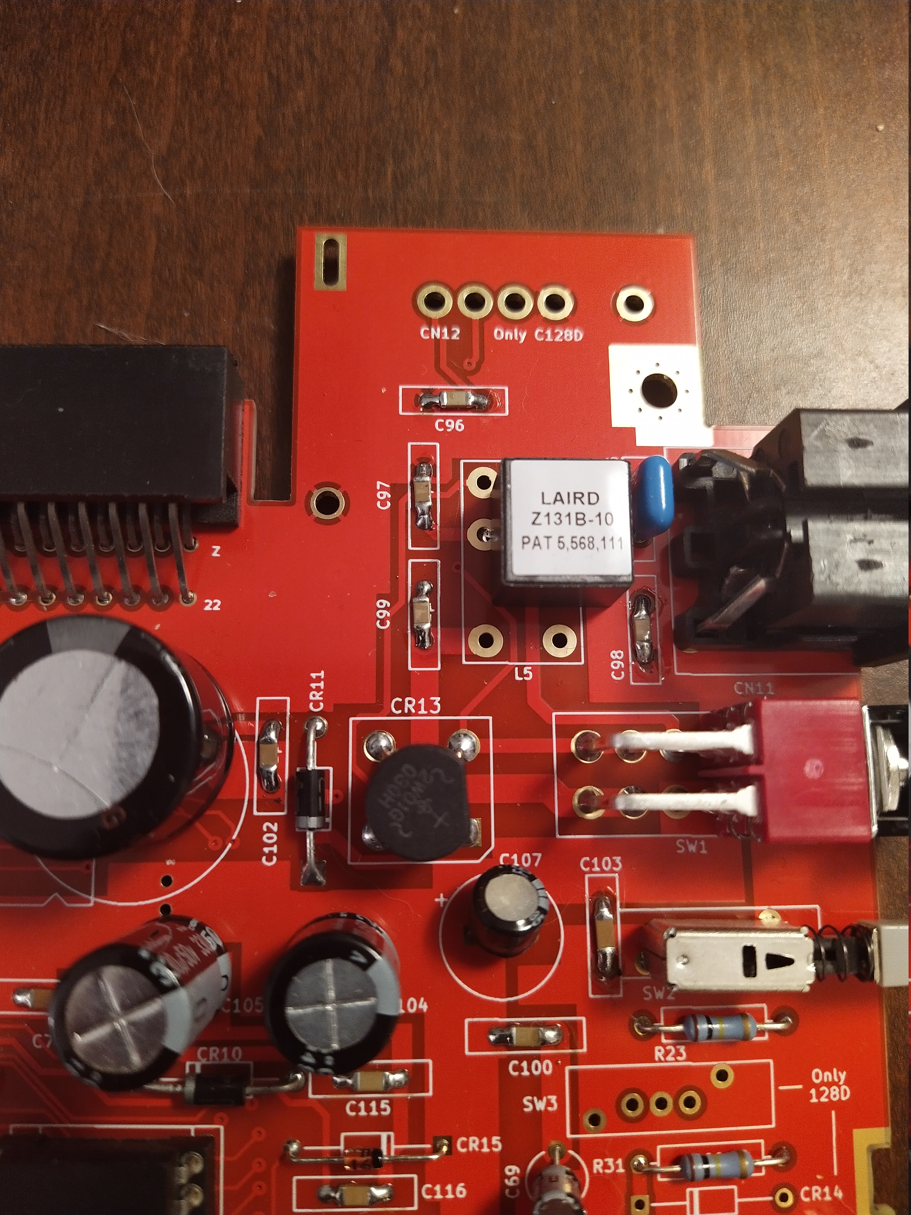
RF modulator
The largest and most obvious of these is probably that the a RF modulator replacement has been integrated.
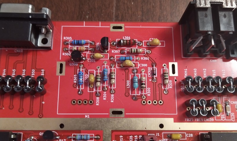
It fits entirely within the footprint of the original RF modulator. If the use of an original RF modulator or another replacement board is wanted, you can leave these components unpopulated, add an isolation layer of paper or plastic and install an original RF modulator instead.
This performs the same job as most of the replacement boards that can be bought, mixing the VIC-IIe:s signals into the Composite and S-Video signals that is available on the A/V DIN connector on the back of the 128. The circuit is the same as the original RF modulator but with the RF component removed which leaves slightly cleaner Composite and S-Video signals.
Jail bar reduction
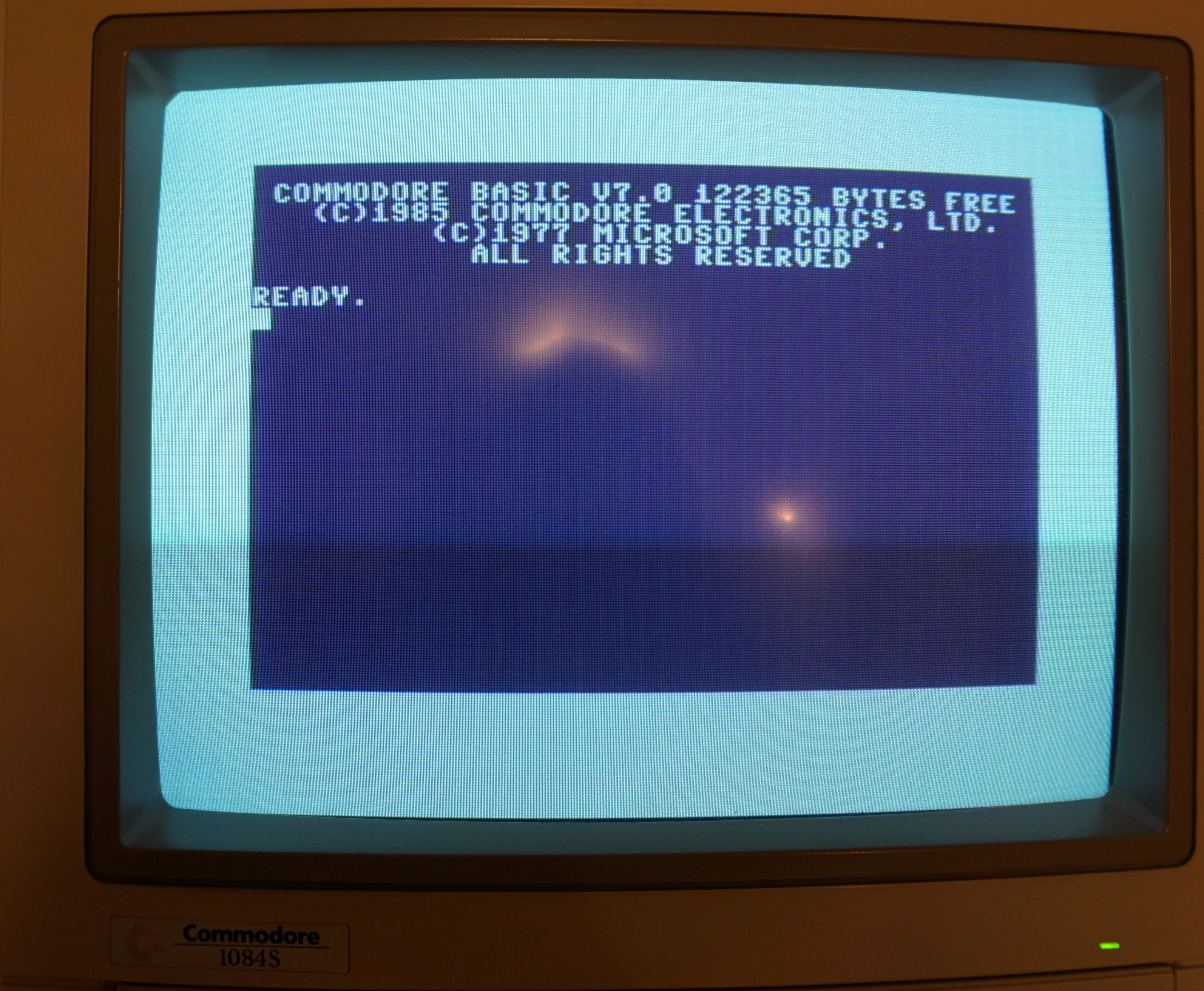
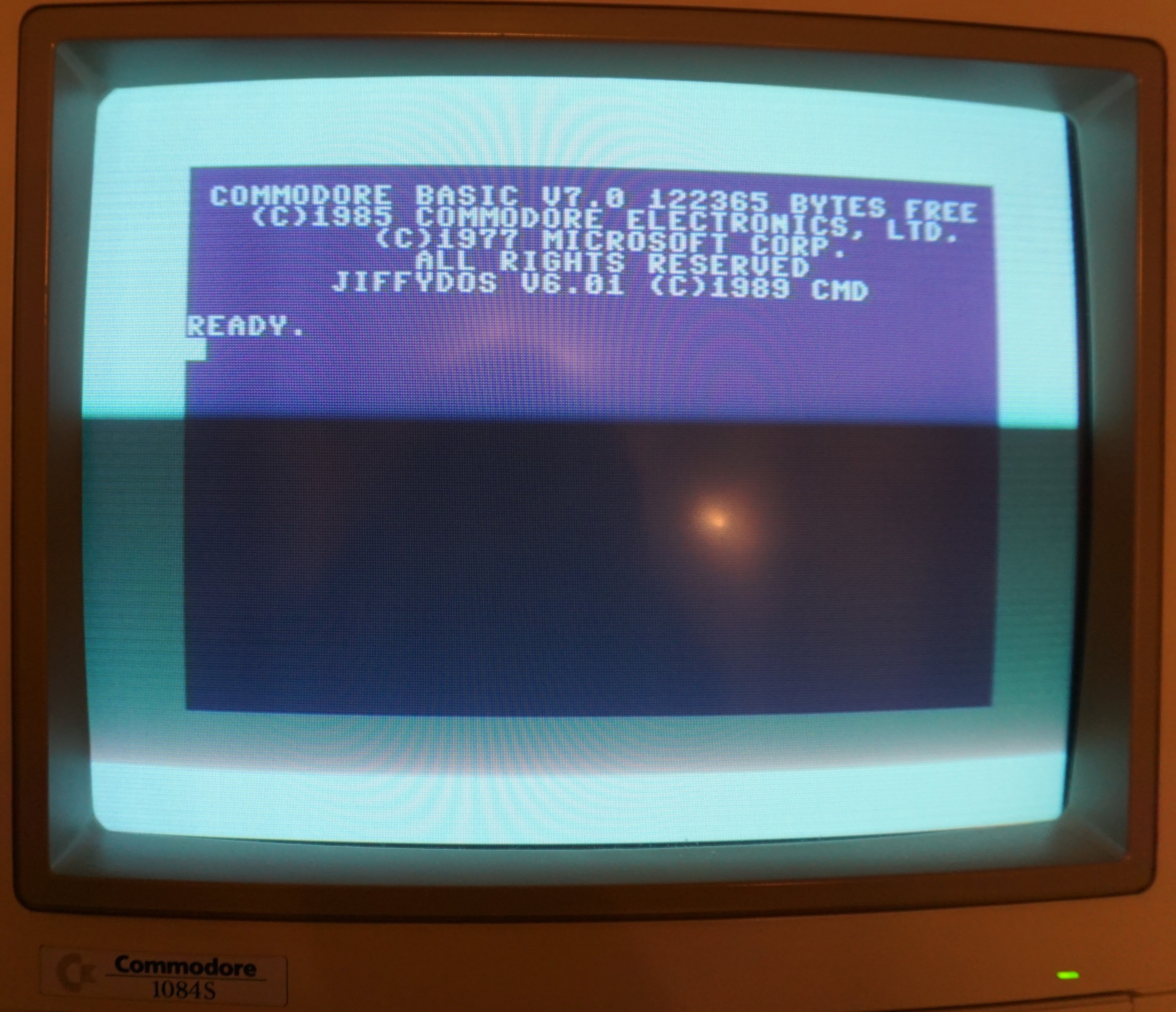
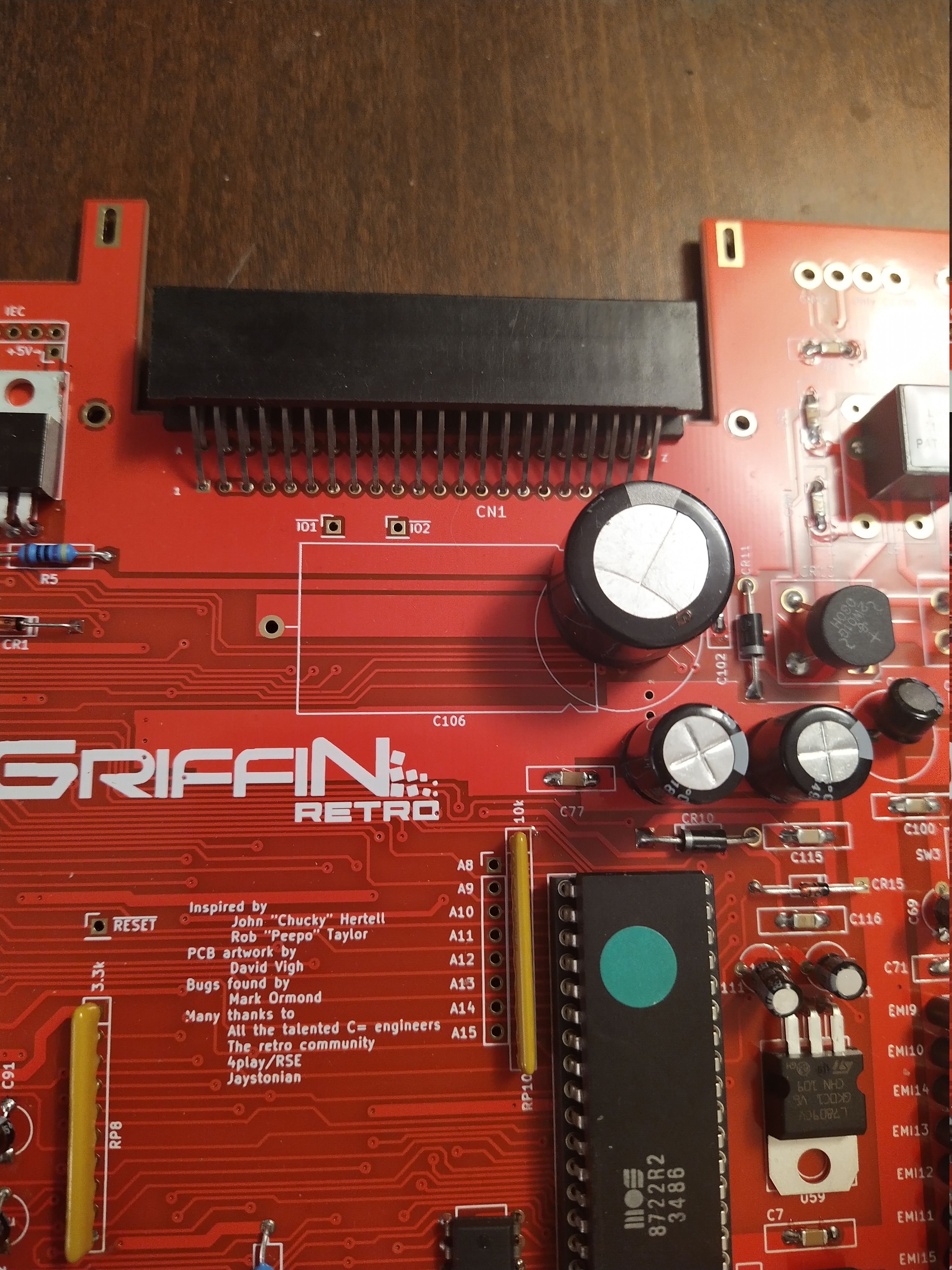
Speaking of video clarity, guard traces were added to the video signal outputs going from the VIC-IIe to the RF modulator. This has made for quite some reduction in visible “jail bars” in the video output as can be seen in the photos above. 1
These changes are not the same as the popular “Clear Video” mods you can find as it doesn’t change the video signals themselves, it just aims to prevent other signals on the board from “leaking” into the video output. As such there are still some faint traces of jail bars left in the output but it’s so faint I have to look for them to notice them.
Built in joystick ESD protection

TVS diodes have been added to the board. These are the only surface mount components in the entire board and they are entirely optional to install. The eagle eyed reader might notice some SMT capacitors in the images shown, this is me using 1206 SMT caps on the through hole mounting places as I find them easier to solder.
They install on the bottom side of the board close to the joystick ports and protect the CIA from ESD damage when swapping joysticks.
Banking jumpers for ROMs
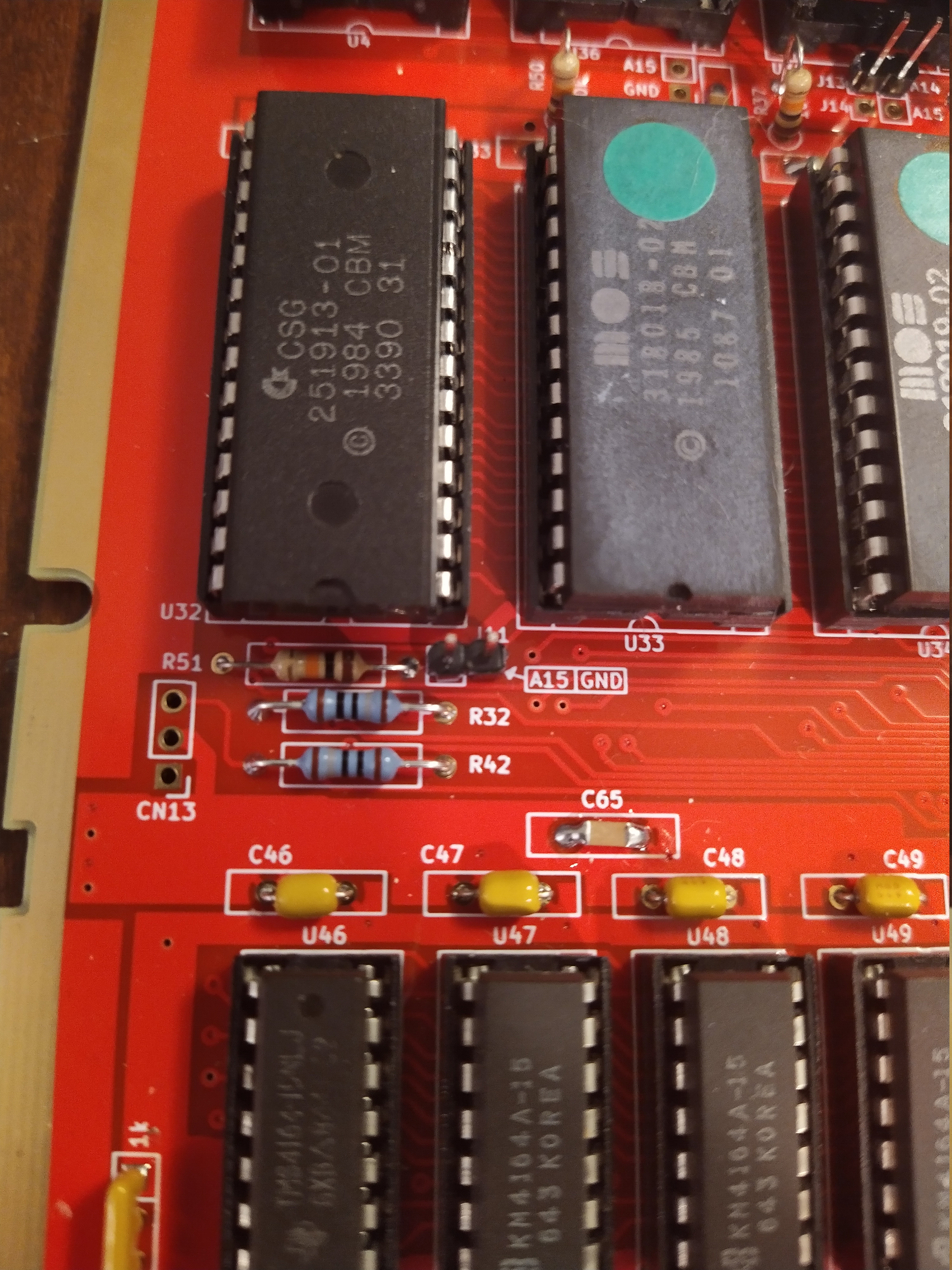
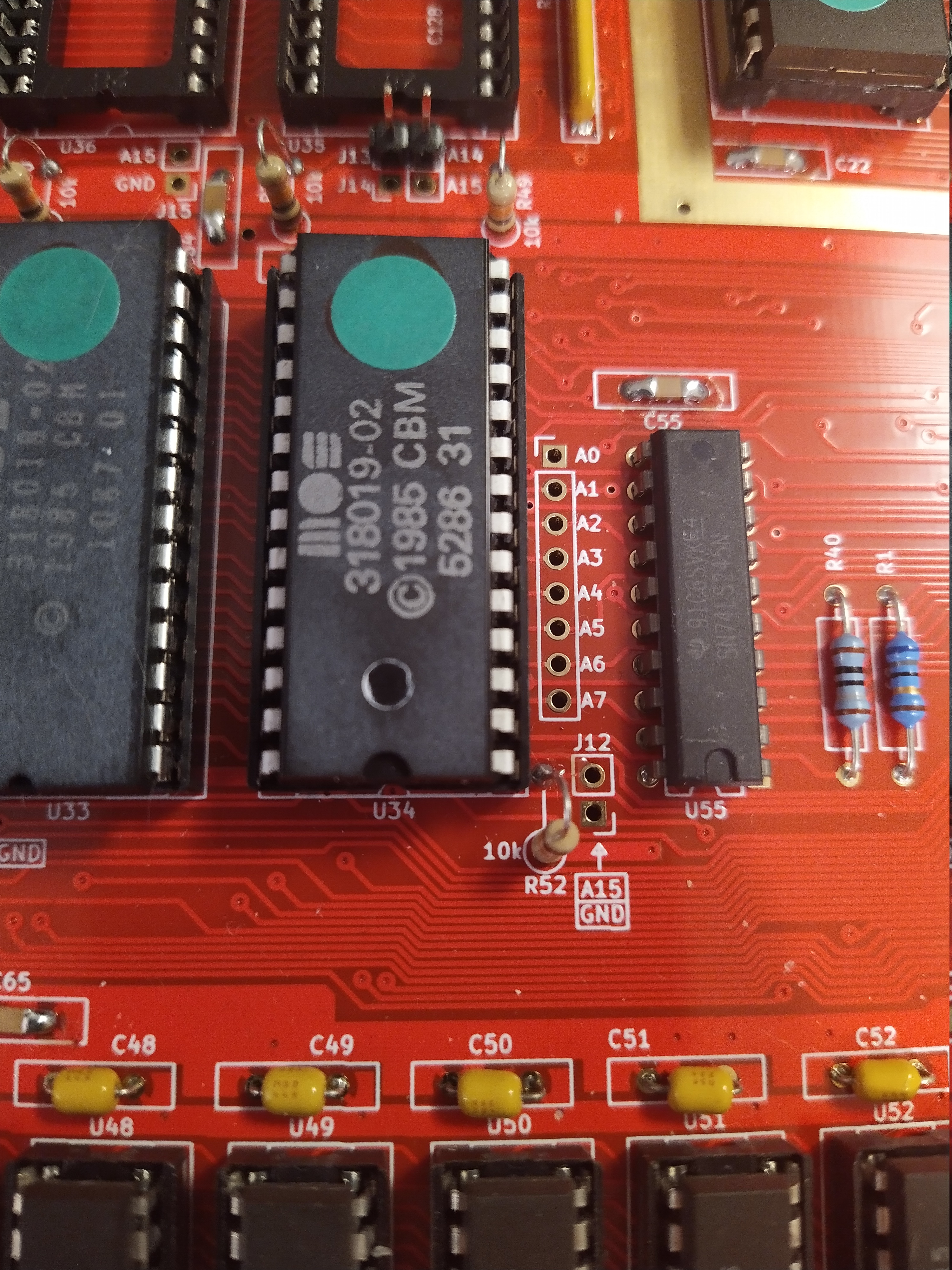
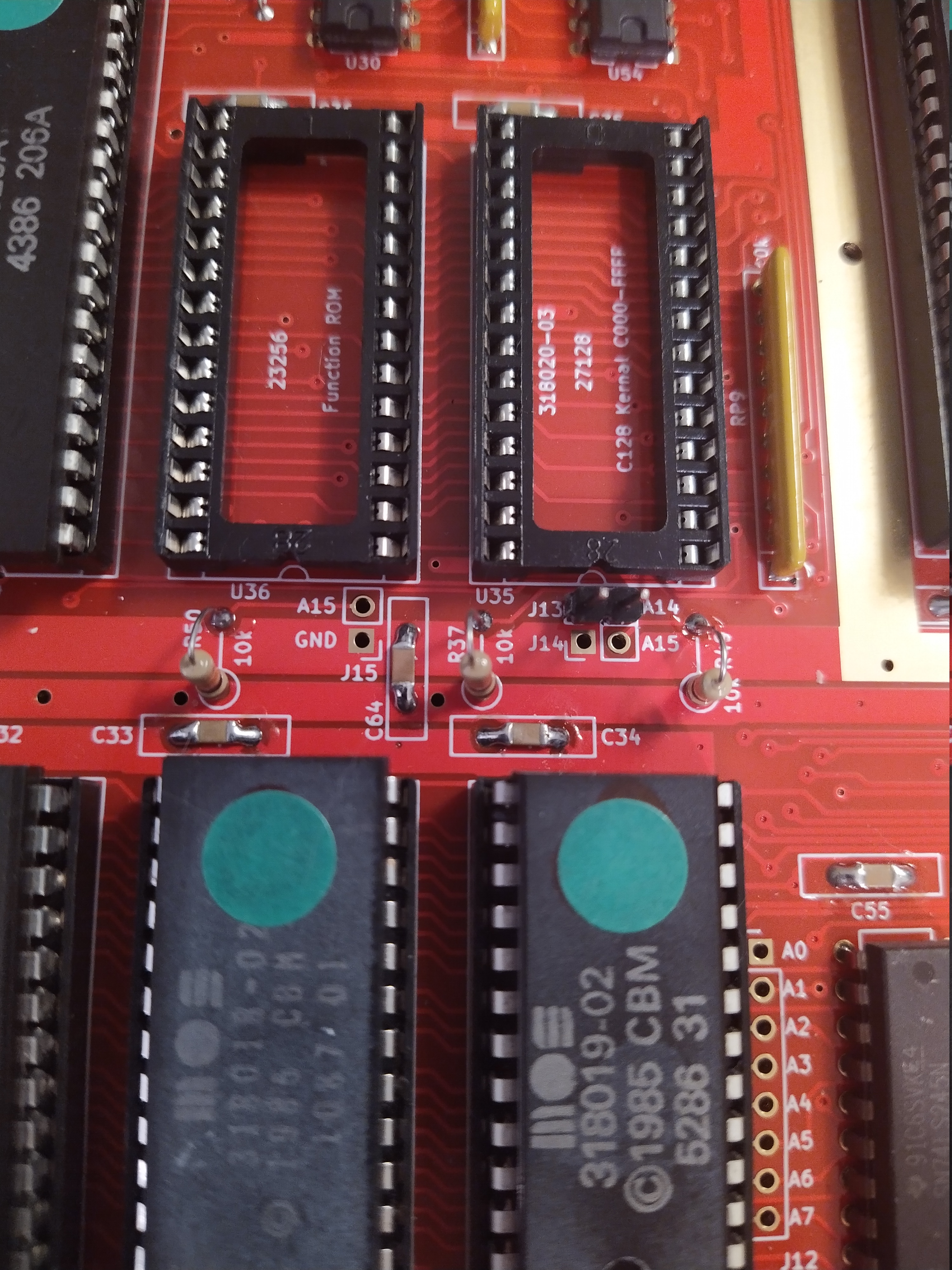
Most of the ROM sockets have had banking jumpers added, allowing to use larger ROMs and switch between banks with a jumper or a switch.
Additionally the board has been fixed so it is now possible to use the larger DCR ROMs without any modifications beside setting the jumpers correctly.

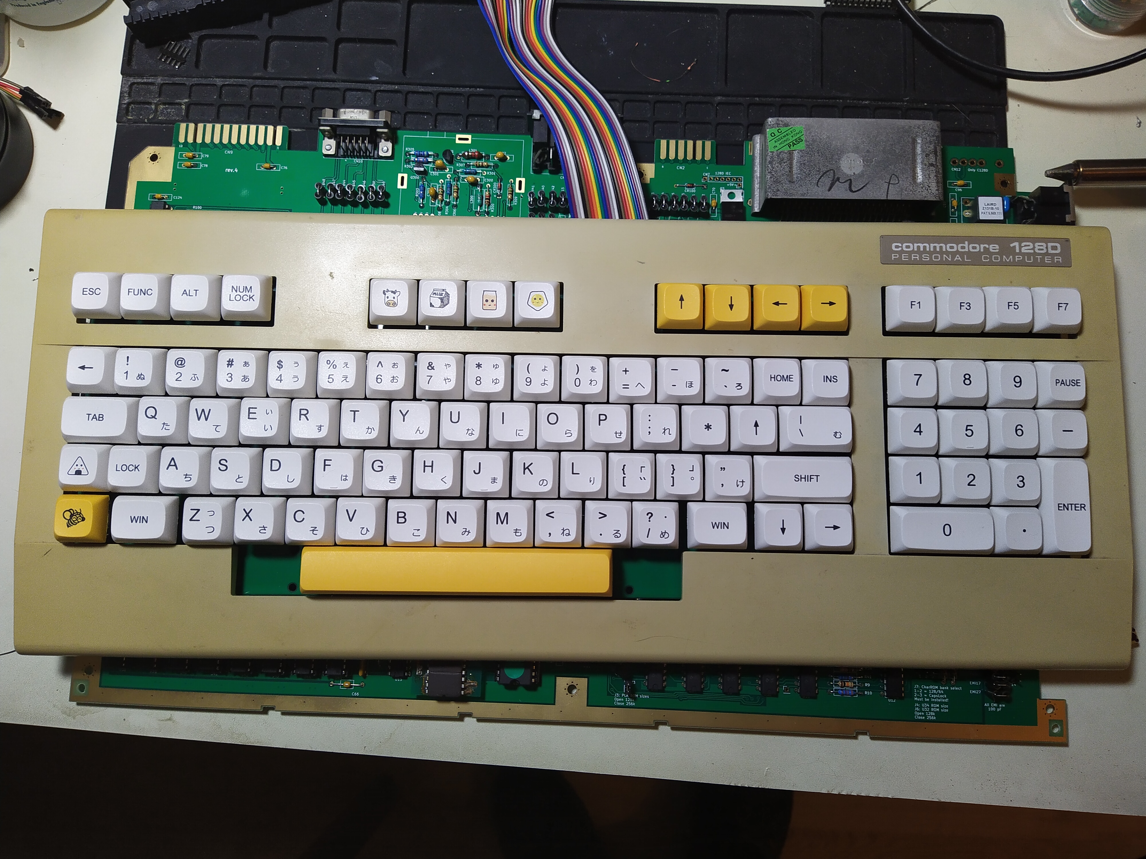
Speaking of jumpers, the underside of the board now has a jumper settings reference show what each jumper does.
Connectors and headers
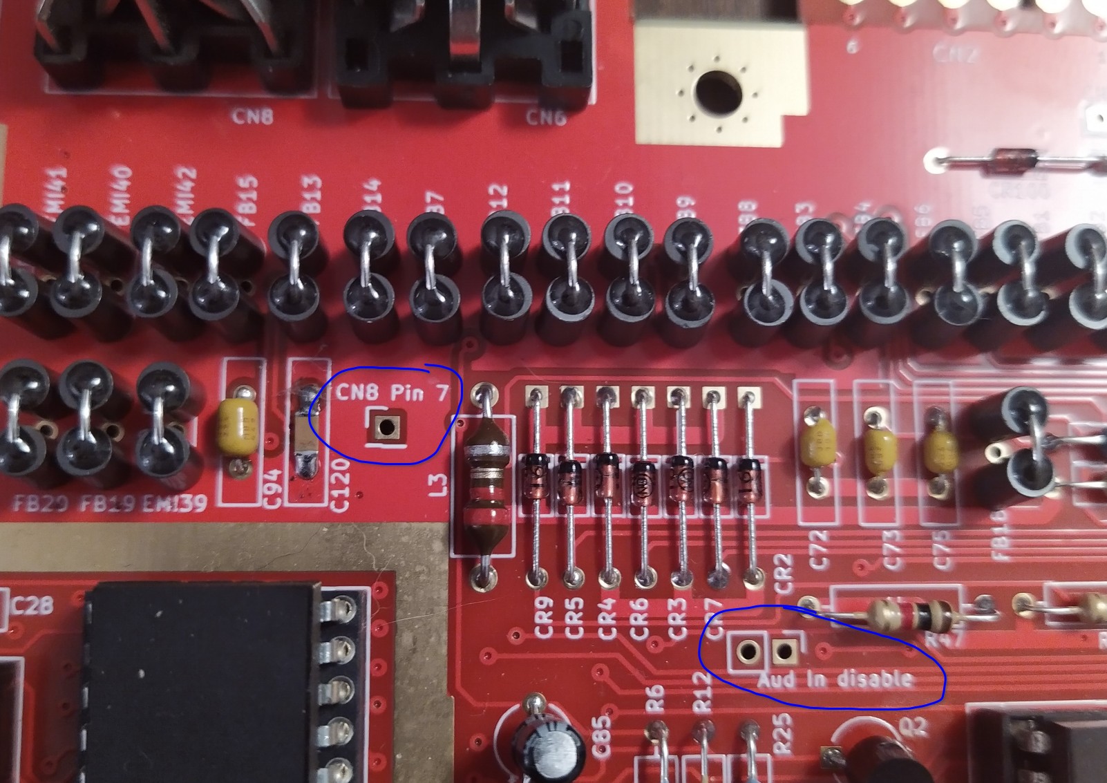
It is possible to install a jumper to ground the SIDs audio input pin to reduce a bit of noise in the audio. This can also be used to connect something to the audio in internally.
Additionally a place to connect to the unused pin 7 of the A/V DIN connector was added, making it easier to use this spare pin for something else such as outputting sound from a dual SID board.
DIN connectors
Speaking of those DIN connectors, additional mounting holes have been added to allow for DIN connectors with differences in the layout of the shielding pins.
Keyboard connector

It will also be used by the mechanical keyboard that is being worked on for the C128 to make it possible to use a straight cable to connect it to the computer, simplifying the connectivity.
Board mounting holes
The PCB mounting holes were slightly out of alignment with the C128 plastic case, this has been fixed making it a straight forward to install the 128Neo in the C128 plastic case.
Edge connectors
The edge connectors on the previous revisions didn’t have a sufficient chamfer, a larger chamfer is now in place making it easier to connect things to the user and cassette ports.
Pin headers
Various pin headers have been added across the board.
- CPU address bus
- IO1 and IO2
- AEC
- 1MHz
- GAME and EXROM
- Restore (e.g. NMI)
- The two spare I/O address decode lines (for the $D5xx and $D7xx ranges)
This is to help with various internal addon boards and projects.
Component changes
Some components have been modified or changed to make it possible to use modern replacements that are still being manufactured.
Line input filter
Radial capacitor
What’s next?
This will probably be the last revision of the C128Neo board but not the end of my work on the C128 as a computer.
As stated above I am working on a mechanical keyboard PCB for the C128, which is nearing completion. This is an open source design and is available under an open source license, it is however not yet finished.
Aside from this the work on reverse engineering the MMU chip continues.
-
I just discovered how hard it is to take photos of CRT screens… ↩︎