Fixes: J7
Here’s another interesting discrepancy between the schematic in the service manual and the actual PCB.
Though neither the jumper of the pin on the ROM it’s connected to is labelled, it is documented as A12.
To understand what’s going on here a bit better we need to look into how the VIC display characters.
VIC-IIe memory banking
Let’s first have a look at how the VIC is using the memory. As opposed to the CPU the VIC can only access 16kB of RAM. This is due to only having 14 address lines, compared to the 16 of the CPU. To enable it to use the full memory range of the computer, the upper two memory lines are connected to one of the CIAs. This allow selecting which 16 kB of RAM that the VIC can see. So far this is identical to how the VIC is connected in the C64. The only major difference is that the C128 MMU can also select which of the two banks of 64 kB this comes out of.
The MMU is controlled using bit 6 of hardware register $d506. This is hardwired to 0 when operating in C64 mode. The CIA register controlling which 16 kB bank to use is $DD00, where bit 0 and 1 control which bank is used. If these extra bits from the MMU and CIA are considered as address lines, we get the following layout:
| bit | source |
|---|---|
| A17 | MMU $d506 bit 6 |
| A16 | CIA $DD00 bit 1 |
| A15 | CIA $DD00 bit 0 |
| A14-A0 | VIC IIe |
Thus allowing the VIC to access the whole 128 kB of RAM present in the computer. For the following discussion we are largely going to ignore most of this and instead discuss what happens inside of that 16 kB bank of RAM that the VIC can address directly.
VIC-IIe screen layout
So, how do we get that nice ‘READY’ prompt onto the screen?
It starts with hardware register $d018 in the VIC. This register is split into two parts, Video Base and Character Base. Each of these parts are setting the upper bits of the address used to access the screen ram and character rom/ram respectively. The Video Base is used to point out where to fetch which characters to render where. The Character Base tells where to fetch what to render for each character.
Since the screen is 40x25 characters, we will need (40 * 25) = 1000 bytes to store the screen. The next larger power of two (for addressing) is 1024. Since the VIC can see 16 kB of RAM, we will need 4 bits to set this base. This is encoded in bits 7-4 in register $d018. The default setting is 0001 which means that the screen data is read starting at $0400 (or 1024 in decimal).
For the Video Base addressing, we can now extend the previous table to:
| bit | source |
|---|---|
| A17 | MMU $d506 bit 6 |
| A16 | CIA $DD00 bit 1 |
| A15 | CIA $DD00 bit 0 |
| A14 | VIC $d018 bit 7 |
| A13 | VIC $d018 bit 6 |
| A12 | VIC $d018 bit 5 |
| A11 | VIC $d018 bit 4 |
| A10-A0 | Screen data |
The layout of the screen is best described using the lovely image from the C128 Programmers Reference Manual:
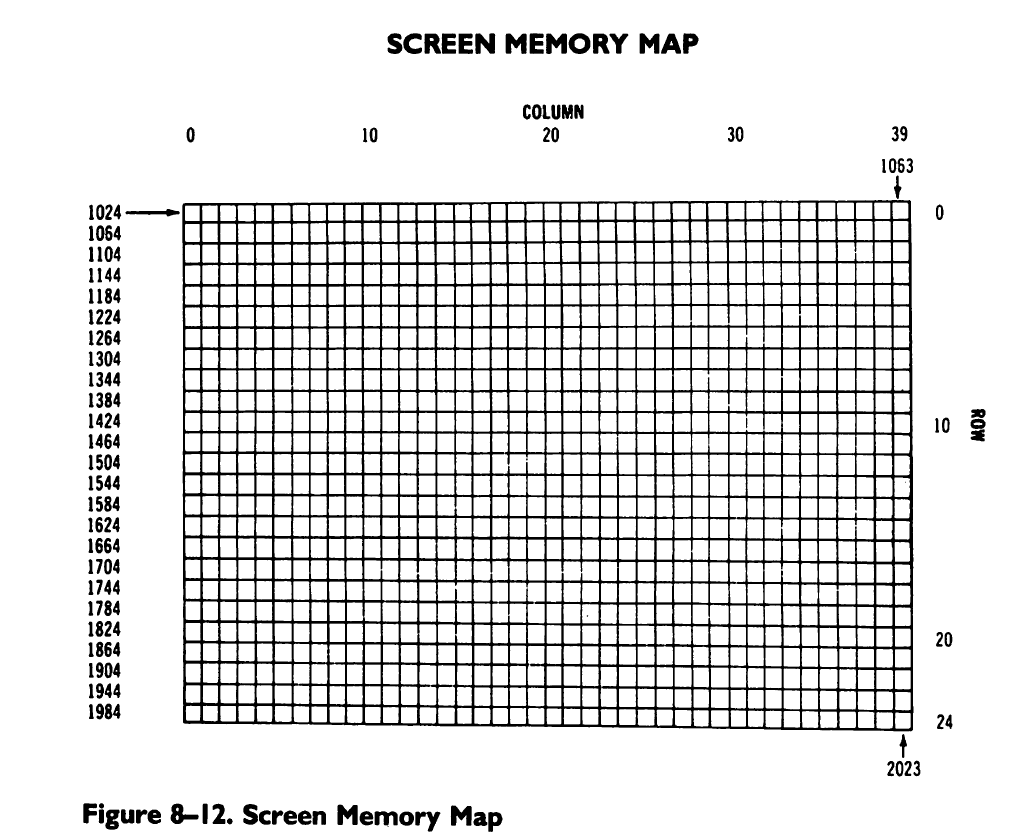
At the start of each line of text, the VIC will fetch 40 bytes from the Video Base into an internal buffer. The address of where these bytes are fetched from is offset by 40 multiplied by which line is being fetched, resulting in the address map shown above.
Each byte will represents which character to render at that position on the screen.
VIC-IIe character memory
Fonts are stored as 8 bytes per character in memory. This is basically a bitmask showing which pixels are to be rendered.
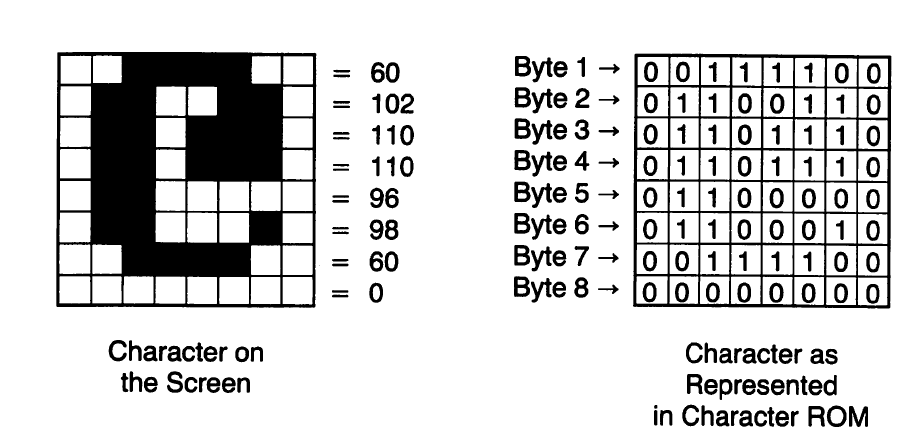
These are stored in memory (ROM or RAM) in a linear fashion, 8 byte per character. When the VIC wants to render a character on screen, it will take the byte from the screen. This is the multiplied with 8 to get an index into the character storage. This means that a full set of characters will take 256 x 8 = 2048 bytes of memory.
If we show the full set of characters used, we get the following matrix:
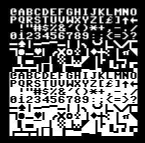
Here we can see that the font has 128 characters in total followed by the reversed version of the characters. Conspicuously absent are any lower case characters, so how do we get those? The solution is that the C64 font ROM is 4 kB, holding two separate fonts. The kernal then reconfigures the $d018 register base address for the character data when you press the Shift-C= combo to change.
This can be shown as a change in the A11 address line:
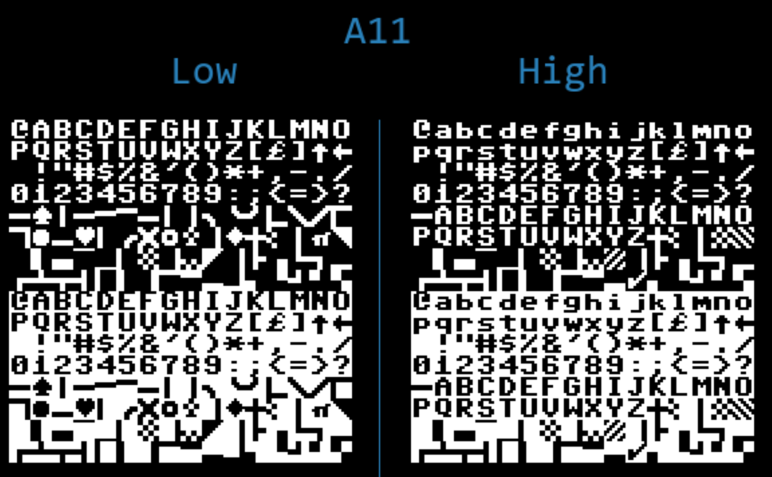
Commodore 128 Character ROM
When creating the C128 they modernized the font. This caused problems with the C64 compatibility, most famously koala paint who would render an enlarged version of the rom font on it’s title screen and then do a flood fill. Since the lower case i has changed the flood fill missed the text and started filling the whole screen. To fix this, they made the character ROM double the size and put the whole C64 font inside in addition to the C128 font.
Having double the ROM capacity also made it possible to have two separate fonts on international machines, such as the Swedish version of the C128, without having to sacrifice being able to use the English font. This is made possible by connecting the CAPS LOCK key to this A12 address line on the Char ROM.
For compatibility it seems they copied the C64 font into both fonts and made one the international one. My guess is they just took the i18n fonts from the local C64s and put it in the Char ROM.
Now we have a Char ROM with the following layout:
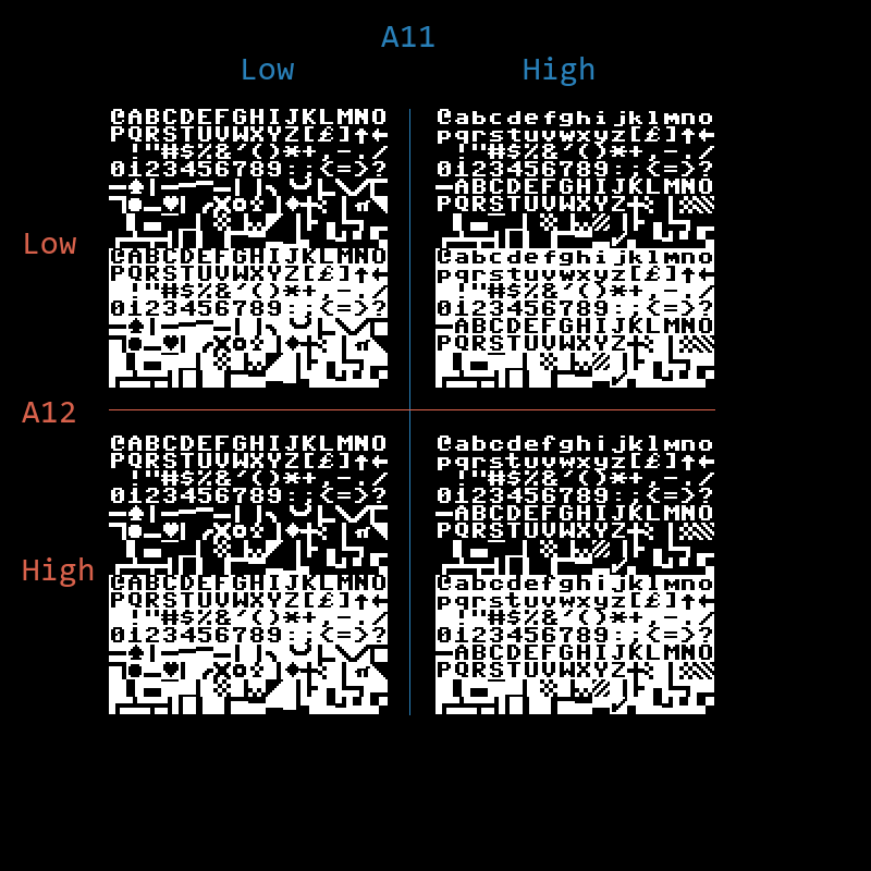
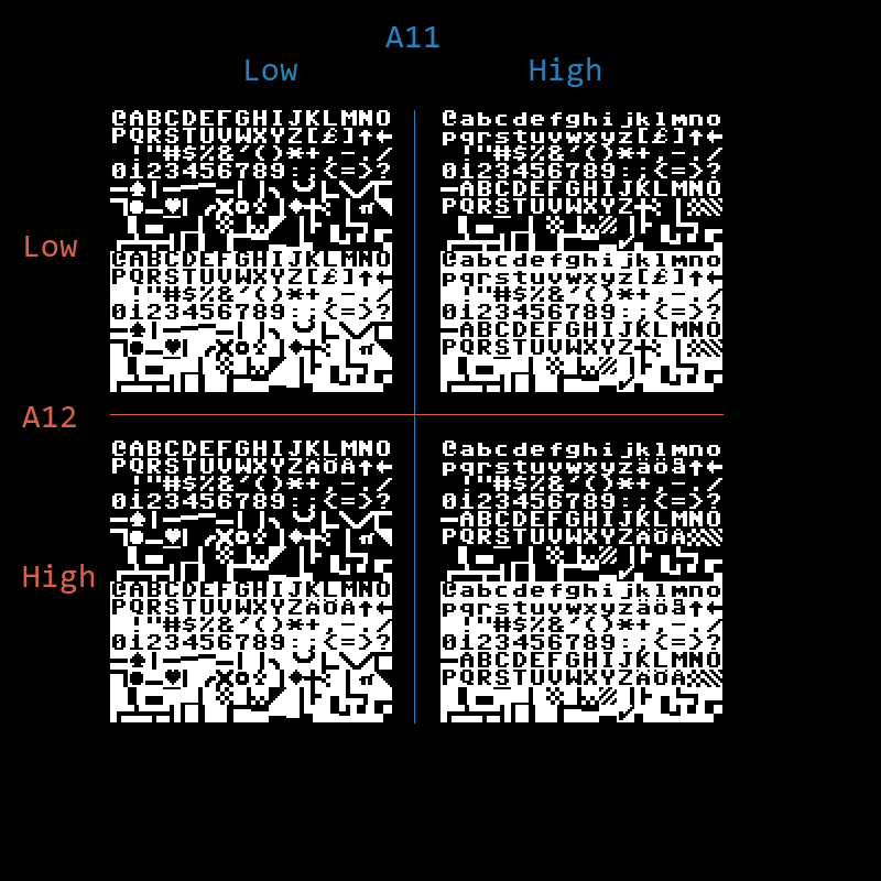
You can tell in the US English ROM that the lower case i is different between the two banks, whereas on the Swedish there’s no difference.
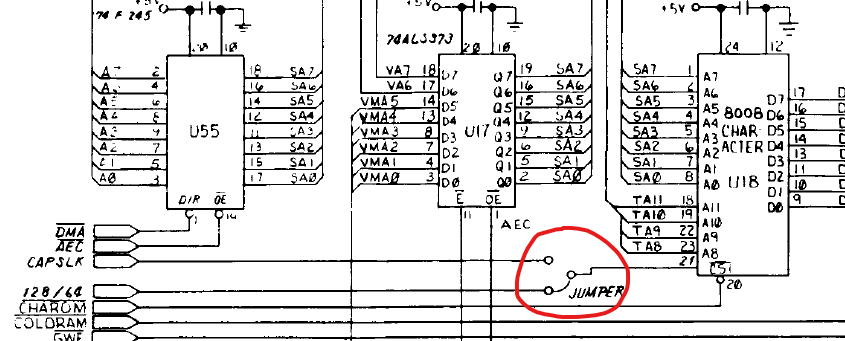
Jumper J7
Now we can finally get to the actual jumper. Jumper J7 is in the schematic to allow selecting which control signal is used for A12 on the Char ROM. Either 128/64 or Caps Lock is used. 128/64 is generated by the MMU chip and the Caps Lock signal comes from the same key on the keyboard.
So far, so good. All normal. Then we have a look at the actual C128 PCB and things start getting a bit interesting.
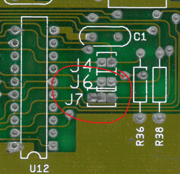

At a first glance, this doesn’t seem to match the schematic at all! Three pads are fine, but the middle is connected to J6 and the left pad is not even connected. What’s going on?
J6 and J4 are used to select the size of the kernal and basic roms, 8 kB or 16 kB. For J6 this means that the lower half would hold the C64 mode ROMs and the upper half would be the C128 mode BASIC. In order to do this, this jumper uses the 128/64 signal as an address line.
So instead of having a jumper between 128/64 and Caps Lock as the schematic would indicate, the 128/64 line is hard wired into the Char ROM. The attentive reader would remember that this means trouble for the nationalized versions of the C128, as on those we need Caps Lock instead.
This was resolved on the production lines (I guess during import) by some cutting and soldering. The right-hand pad of J7 does hold the Caps Lock line, so a cable was soldered to it. The other end of the cable was soldered in to a via close to the A12 of the Char ROM, and the line connecting it to 128/64 was cut.
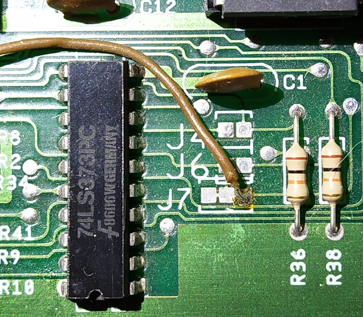
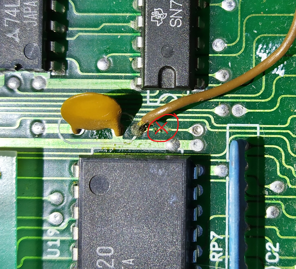
(Yes, I know the solder joints are terrible. They are 34 years old. It works, it wasn’t me :) )
The fix
Finally, after all this waffling about we can get to the actual fix.
J7 was reworked to have both Caps Lock and 128/64 on the respective pins and the middle wire was connected to A12 on the Char ROM.
Quick and easy to say, but the PCB layout of the C128 is a bit crammed so routing this in was not easy. To make it even more fun, there were more things connected to the 128/64 as it was routed along the PCB.
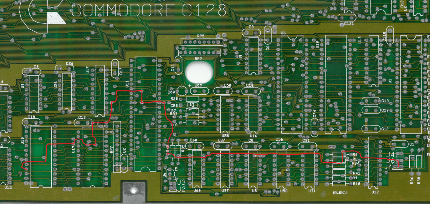
J7 to the Char ROM on the Commodore PCB.
Fortunately, this is not a high speed signal so making it take the long route was a viable option.
Due to the things connected along the route, I had to rework both the J7 connection and the 128/64 line.
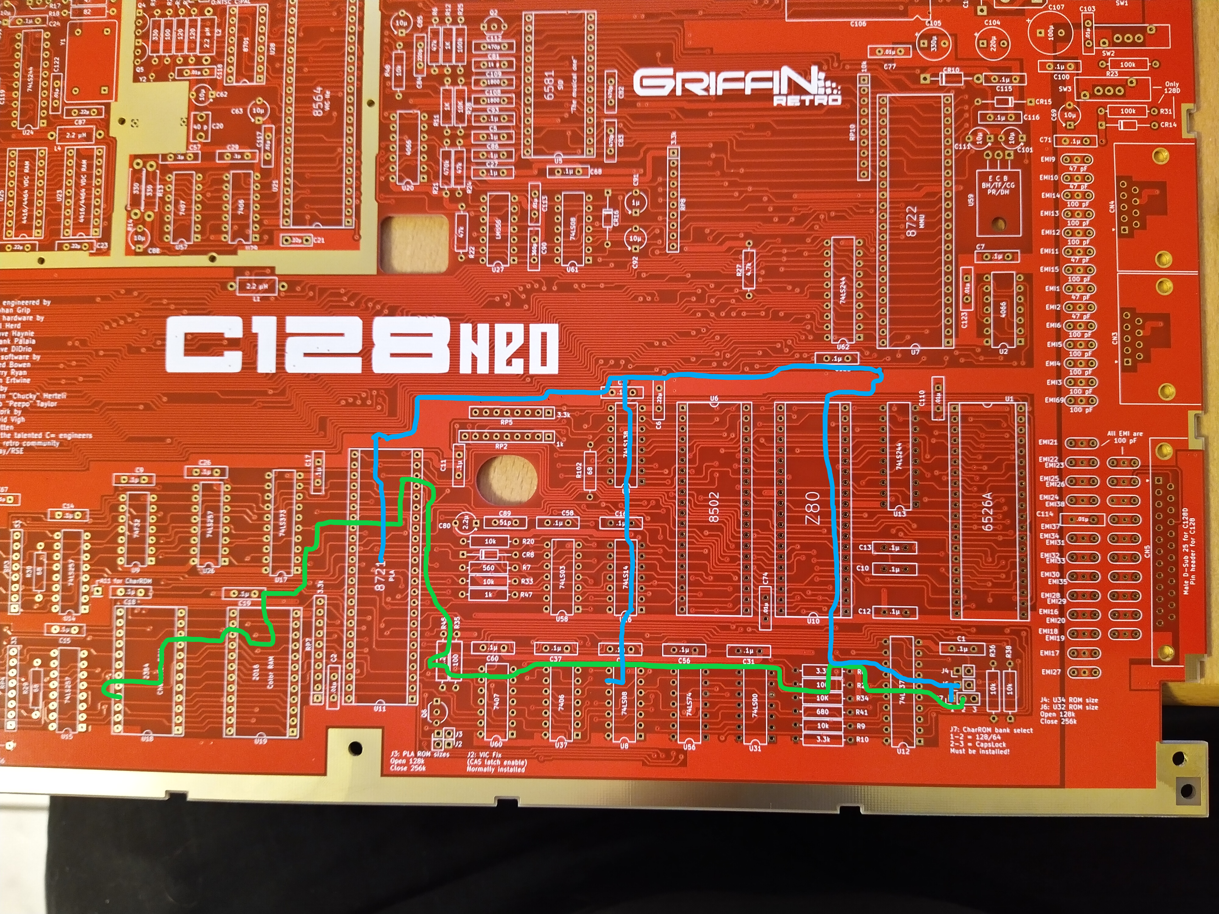
128/64 is in blue and the J7 middle pin is in green.
That’s all I have for this time, join me next time for more adventures in 128-land!